Installing Hardware
This topic covers installing the Galaxy 635-DSI Board and the AD-Series PIM.
topics covered
Materials Needed to Install PIMs
Wiring AD400 PIMs to 635-DSI Board
Wiring AD400 PIMs to 600-DSI Board
Materials Needed to Install PIMs
IMPORTANT: Be sure you reviewed the Schlage Requirements for ADSeries integration.
IMPORTANT: You must properly install the Galaxy Controller with the 635-CPU board and 635-SI board following the hardware instructions in Chapter 2 of the Galaxy Hardware Install Guide.
The Galaxy Hardware Panel & CPU
-
Galaxy Hardware & Minimum Flash Requirements for office mode and privacy mode.
-
635 CPU Board – with min. v10.4.8 .S28 flash code (or higher)
-
635 DSI Board – with min. v10.4.8 flash (or higher)
-
-
You must configure the 635 CPU & DSI using the following tools ...
-
the 635 Hardware Guide for instructions.
-
a PC/Laptop with a COM Port
-
HyperTerminal (or suitable emulator program such as Putty)
-
a Serial Programming Cable to configure the correct network parameters for the CPU and the board ID on the DSI Board.
-
635 Web Configuration Tool (see the 635 Web Config Tool Guide)
-
How to wire the AD400 PIM to the 635-DSI Board
A DSI board can have up to 16 doors on each RS-485 Section.
There are two (2) RS-485 Sections on a DSI board. Multiple 485 PIMs can be connected in a daisy-chain fashion to the DSI RS485 Section.
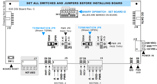
Before mounting DSI inside Controller ...
Before mounting the DSI Board inside the Controller, you must do a few steps.
-
Set the 635-DSI Board ID with the binary dipswitch:
The binary values are marked on the board above the dipswitch (1, 2, 4, 8, 16 are the binary markings).
The board markings also indicate the dipswitch position that sets that value (positions 8, 7, 6, 5, 4 are for binary addressing).EXAMPLE
-
For Board ID 1 set dipswitch position 8 to ON (all others off).
-
For Board ID 2 set dipswitch position 7 to ON (all others off).
-
For Board ID 3 set dipswitch pos. 8 & 7 both ON (all others off).
-
The board comes factory set to Board ID 16 (sw pos. 4 ON).
-
-
Set Termination Jumpers (JP4/JP5) to “TERM” only if the section is at one extreme end of the 485 wiring run.
Otherwise set them to "OPEN".The 485 Sections operate independently so it is possible for one section to need termination set while the other is set open. This depends on your installation. You will need to install termination jumpers at both extreme ends of the wiring run. If you set the board's termination jumper, then you need to install Termination Resisters on the other line end.
-
When you install the board, you can do a warm RESET to initialize the Board ID. You should follow the Hardware Guide instructions for applying power and flashing the board.
-
On every PIM unit you must install the 2 black jumpers (2/4 Wire Jumpers).
-
Remove the 2-piece orange connectors and use screw terminals to land the wires from the PIM to DSI ports:
PIM TDA- to DSI A; and PIM TDB+ to DSI B; use wiring diagram below. -
You must ground the shielding on every segment of RS-485 cable on one end only. The following diagram shows shielding for the 1st segment grounded at the controller end.
-
The PIM unit should be powered on a separate power supply.
Figure 7 – Wiring PIM to 635-DSI Board
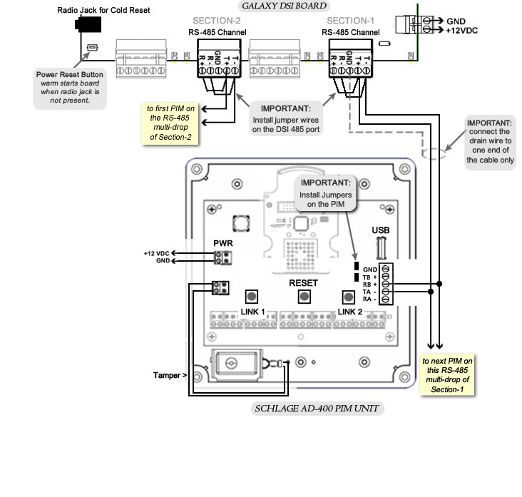
How to wire PIMs to 600-DSI Board
IMPORTANT: The 600-DSI Board will not support office mode or privacy mode..
-
A 600 DSI board can have up to 16 doors on each RS-485 Section.
-
There are two (2) RS-485 Sections on a DSI board.
-
Multiple 485 PIMs can be connected in a daisy-chain fashion to the DSI RS-485 Section.
IMPORTANT NOTES
-
Install jumper wires on the DSI ports [ T – to R – ] and [ T + to R + ]
-
install the two black jumpers on every PIM unit (see diagram below).
-
Land wires from DSI T- to PIM R+ ; and DSI T+ to PIM T- (use diagram below).
Ground the shielding on for every segment of RS-485 cable on one end. The following diagram shows shielding grounded on the controller end.
-
The PIM unit should be powered on a separate power supply.
Wiring PIM to 600-DSI Board