Configure Reader Properties
This topic covers configuring reader properties for "DSI-based readers" that are wired or wireless (including ASSA, Avigilon, Salto, Schlage, etc.).
See the Galaxy Software User Guide for in depth instructions on reader settings.
INTRODUCTION
Configuring the DSI-based reader (wireless or wired) is done in the Reader Properties screen. Some options and features are not available for the DSI-based readers, and therefore will be disabled in the screen.
TIP: The PIM/Reader Linking Template can be used to help you map your readers. Filling out the template will document which readers are connected to which controller boards and where the readers are located or which room/door they are controlling.
PREREQUISITES
-
You must sign-in to SG with a master-level password to configure readers.
-
You must have already installed and programmed your hardware (PIM/HUB Numbers & Reader Numbers).
-
You must have added the DSI Board in the Controller Programming screen.
-
You must have enabled the correct reader numbers in the Serial Channels screen.
-
See Appendix for a list of options that are not supported by wireless readers.
-
You must configure the correct PIM # (or Hub #) that the reader is really linked to.
For wired readers (AD300) the system reserves the reader number as its PIM number.
-
On a Schlage "mixed network" (AD300+AD400), an AD400 Reader cannot use a PIM number that is reserved for AD300.
Example: If Reader 1 and 2 are AD300s, then the AD400 Readers can link to a PIM#3 or higher.
-
Open Reader Properties screen: Configure > Hardware > Reader Ports
-
Select the Cluster name and Controller name that your DSI-Board is connected to.
-
Select the desired Reader from the [Reader Name] droplist;
(the default system name identifies the Section# - Reader# ). -
Click the Edit button.
-
Enter a custom Reader Name that is meaningful and describes the reader location (i.e. Entrance, Closet, etc.).
Notice that the default system name is still displayed above the name field - and shows the hardware mapping for the Cluster/Controller #, Board #, Section # - Reader ID.
TIP FOR NAMING READER: Consider including text that identifies special modes, schedules or features that apply to the door – such as "Restroom (Privacy Mode)" or "Front Door (Office Mode 9a-6p)", etc.
This step describes the Reader Type field for DSI-based readers. The reader-type is configured in the Serial Channel Properties screen. Non-DSI Readers would set the reader type here.
Important Notes
-
All readers on the same DSI-section (or RS485 network run) must use the same card format (or reader type).
-
To change the Reader Type (card technology), return to Serial Channel Properties screen.
-
The Reader Type field is disabled (locked) for any DSI-Based reader.
You can see which type was selected in the Serial Channel screen.-
PIM Wiegand
-
PIM ABA
-
Setting the PIM# is based on which ID you assigned when you installed the PIM.
Important Notes
-
After completing Reader Properties, the reader settings must be saved (applied) loaded to the access control panel.
-
Any options that are locked are not supported by Wireless Readers, or not supported by your brand . See Feature Table for quick reference.
-
You can identify your Reader Number by the last digit of the Default System Name, located above the Reader Name field – e.g., “Brd 5, Sect 2-4” is Reader 4 on Section 2.
-
If an AD300 Reader is installed, the system programmatically reserves the PIM #. Even though there is no PIM physically installed, the system counts the AD300 Reader ID as its PIM ID – i.e., Reader #1 gets PIM#1, Reader #2 gets PIM#2, etc. This is true both for dedicated AD300 Only and for mixed AD300/400 networks.
-
If an AD400 Reader is installed, you must set the PIM# to the value the of the PIM that the Reader is linked to. The system will experience undesirable behavior if the PIM# is mismatched.
-
On a mixed network, an AD400 Reader cannot use a PIM# that is reserved for AD300.
-
If an NDE/LE Reader is installed, you must set the HUB# to value of the HUB that is linked to the Reader you are configuring. The system will experience undesirable behavior if the HUB# is mismatched.
-
On the General Options tab, set the PIM# Field based on the reader type:
-
For an ‘AD300 Only’ on DSI Section = PIM# Field is disabled –
Galaxy programmatically reserves the Reader ID as the PIM# for each AD300.
-
For an ‘AD400 Only’ on DSI Section = PIM# Field is enabled –
set the PIM# to the correct PIM ID that the AD400 Reader was physically linked to during installation.Use the PIM/Reader Mapping table to help you set the PIM#.
(The PIM# may not match the Reader# but must be the correct PIM.)

-
‘AD400 & AD300’ (mixed) = set PIM field according to the Reader type –
-
AD300 = set the PIM Number must match the AD300 Reader#.
For example: AD300 #1 = PIM #1, AD300 #2 = PIM #2, etc.
The Reader number is the last digit in the default System Name. -
AD400 = set PIM# to the linked PIM ID (linked during installation).
AD400 readers cannot use a PIM# that is reserved for an AD300 reader.
Use the PIM/Reader Mapping table to help you set the PIM#.(AD400 PIM number must be the PIM that is linked to the reader)

-
-
On the General Options tab, set the PIM# Field based on the reader type:
-
For an ‘AD400 Only’ on DSI Section = PIM# Field is enabled –
set the PIM# to the correct PIM ID that the AD400 Reader was physically linked to during installation.
Use the PIM/Reader Mapping table to help you set the PIM#.
(The PIM# may not match the Reader# but must be the correct PIM.)

-
‘AD400 & AD300’ (mixed) = set PIM field according to the Reader type –
-
AD300 = set the PIM Number must match the AD300 Reader#.
For example: AD300 #1 = PIM #1, AD300 #2 = PIM #2, etc.
The Reader number is the last digit in the default System Name. -
AD400 = set PIM# to the linked PIM ID (linked during installation).
AD400 readers cannot use a PIM# that is reserved for an AD300 reader.
Use the PIM/Reader Mapping table to help you set the PIM#.(AD400 PIM number must be the PIM that is linked to the reader)

-
-
Set the [Inside Push Button Function Mode] to the appropriate mode “Office Mode”. .
-
For NONE (No MODE) = Set value to "None" –
-
For OFFICE MODE = Set value to "Office Mode" –
You may want the Reader Name to reflect that office mode is available at this door for Operator clarity.
See more information about How Office Mode Works ...
-
For PRIVACY MODE = Set value to "Privacy Mode" –
You may want the Reader Name to reflect that office mode is available at this door for Operator clarity.
See more information about How Privacy Mode Works ...
-
Next Steps
More about Office Mode (optional wireless feature )
More about the Privacy Mode (optional wireless feature)
Configure Schedules (next)
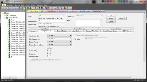
These options and the schedules must be configured in the SG software, then saved (applied) and loaded to the access control panel. The Schedules tab contains fields that affect the timing of the locking and unlocking at the reader. Disabled (grayed) features are not available for Schlage Wireless readers.
Important
-
Schedules must already be configured before you can assign them.
-
The Schedules tab contains fields that affect the timing of the locking / unlocking at the door.
-
Disabled (grayed) features are not available for Wireless readers.
|
Auto Unlock Schedule: When the assigned schedule becomes active, the door or Wireless Reader will receive an unlock command from the access control panel (at the top of the minute). Door will remain unlocked until the schedule expires. When the schedule becomes inactive/expires, the door will receive a lock command from the access control panel and the door will remain locked. Operator commands can lock, unlock, pulse, disable/enable the door as appropriate. The door will remain in the state that was issued by the operator command until another command is issued or until the schedule cycle changes. Also, holidays can affect the unlock schedule. Schedules and Holidays must be created and loaded the control panel. An auto-unlock schedule is used when a door should always unlock and relock at a specific time (e.g. 8am to 5pm). During the unlocked portion of the schedule, the door is open and no card access is required. During the locked portion of the schedule, an access card must have ‘valid access privileges’ in order to open the door. |
|
(OFFICE MODE) Auto Unlock Schedule: behaves differently during OFFICE MODE. When configured, the unlock schedule will determine when Office Mode is available to the user. When unlock schedule is active/in effect, a user can activate Office Mode and door will remain unlocked (open) from the outside. When unlock schedule is inactive/not in effect, Office Mode is unavailable, and door remains locked and requires valid access credentials. |
|
(OFFICE MODE) Crisis Mode for Auto Unlock Schedule: applies only to OFFICE MODE feature. When this crisis mode field is set to the same schedule as the unlock schedule field, then crisis mode will not affect the reader – the reader will remain in the same state/behavior during a crisis mode. If you want the crisis mode to change the behavior of the reader/door, then set the crisis schedule field to the schedule that you want the door to follow during a crisis situation (i.e. Never = locked and Always = unlocked). |
|
PIN required schedule: not available for Schlage Wireless readers. |
|
Disable Forced (schedule): when selected, the system will not report a door forced condition at the door. |
|
Disable Open Too Long (schedule): when selected, the system will not report a ‘door open too long’ condition at the door. This could be helpful during certain times when a door must be open for an extended period of time on a routine bases (e.g. a loading dock). |
|
Reclose Within (mm:ss): the default is 15 seconds. This is the amount of time the controller will wait for the door contact to close at the door before generating a ‘door open too long alarm’. |
Reader Properties: Configuring the Timing/Schedules

Disabled or grayed out options are not supported.
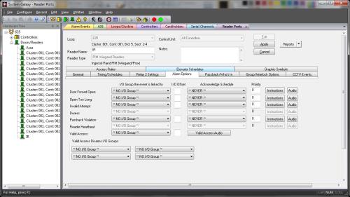
Several device conditions can be configured to generate an Alarm Event in System Galaxy. The conditions are: Door Forced, Open Too Long, Invalid Attempt, Valid Access, and Passback Violation.
An alarm event is generated when a condition occurs at a door/reader that is configured to generate an acknowledgeable alarm. The alarm event displays in the Alarm Event window in the order it occurs unless an alarm priority is assigned. IF an alarm priority is assigned, the alarm message appears in the Alarm Event window sorted in the order of the assigned priority number.
Important
-
These options, and any I/O Groups on which they rely, must be saved (applied) and loaded to the access control panel.
-
(optional) You can assign an I/O Group to the condition. This is not required since Alarm Options are independent of I/O groups.
-
(optional) You can also assign priorities to the Alarm Conditions.
-
The Acknowledge checkbox must be checked to make the event display in the Alarm Event window. This is also required for Priority sorting to apply.
I/O Groups: The drop-down list shows all the available I/O Groups. By default, the field is set to **NO I/O GROUP**. When an I/O Group is selected, that I/O group will be activated whenever the condition occurs on the reader. I/O groups are used to activate outputs associated with the alarm condition.
I/O Offsets: This field contains the I/O Offsets for each condition.
Acknowledge: Select (check) this checkbox if the condition should appear as an alarm event (in alarm events window).
Priority: The Acknowledge check-box must be selected before Priority will apply. The priority field is an optional numeric field that accepts a value equal or less than 9999. This is the priority level of that will be assigned to the alarm event. Priority affects the order of the alarm events in the Alarm Events window. Alarms with higher priority number are sorted to the top of the screen regardless of the order they occur.
Instructions: The Acknowledge check-box must be selected before Instructions will apply. When this button is clicked, a window appears in which you can type in text instructions for responding to the alarm event.
Audio: The Acknowledge checkbox must be selected before Audio will apply. The location of files must also be set up in the Multimedia tab of the Workstation Options window (Configure > Options > Workstation Options > Multimedia tab). One .wav file can be selected to play when the alarm event occurs.
Reader Properties: Configuring the Alarm Options

Disabled or grayed out options are not supported.
Some options may not be available for a wireless reader, or for a wireless reader that has office mode or privacy mode assigned.
-
You must configure Schedules and Areas before you can set up these options in the Reader Properties screen.
-
See the Software User Guide for greater details.
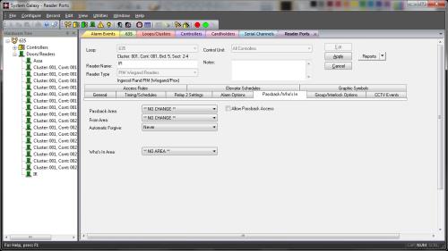
Reader Properties: Configuring the Passback/Who’s In

Disabled or grayed options are not supported.