Hardware Installation
This topic describes how to install Galaxy Hardware (controllers and boards) at the Customer site and program the hardware to communicate with the cloud server.
Topics featured
Configuring Daughter Boards & Verifying Flash
Overview and Requirements
These instructions describe installing and programming ‘one board at a time’ (via the 635 Web Configuration Tool ) before installing the next board. Optional instructions for using TeraTerm to program boards are found in the 635/600 Hardware Installation Guide.
CPU Programming Requirements
-
You must have your Cloud Onboarding Document because it includes information you need to program the CPU board — such as the Event Server IP Address, Remote TCP Port#, and Encryption Passphrase .
-
You must have already created your Cluster in the System Galaxy Loop/Cluster Programming screen.
-
You must know whether you are using DHCP or a Static IP for the controller CPU programming:
-
DHCP you can keep the factory default IP settings.
-
Static IP (recommended) you must know the IP Address, Subnet, Gateway that are appropriate for the Customer’s Network scheme.
-
-
When using the Web Config Tool, the panel door must be open (tamper switch “active”) to program the 635-series CPU.
Equipment & Materials:
-
Laptop – for programming and diagnostics.
-
Multimeter & hand tools
-
A Programming Tool & Cable to configure boards (see table below) …
|
Programming Tool |
Cable |
Connection Options |
|---|---|---|
|
Web Configuration Tool (opens in a browser) |
Cat5e cable
|
|
|
DOWNLOAD the 635 Web Configuration Tool |
||
|
|
||
|
RS-232 |
|
|
|
DOWNLOAD the TeraTerm Emulator |
||
635-series Hardware Install
This section provides instructions on how to install the System Galaxy hardware.
Install a Control Panel
|
!
|
IMPORTANT WIRING SAFETY:
Failure to observe safety precautions can result in equipment damage, injury, electrical shock, or incorrect operation. |
|---|
-
Mount the controller to the wall in a clean dry place and apply power to power supply only.
Do not apply power to the boards, yet. See 635-Hardware Install Guide / Chapter 2 Step-2. -
Apply Power to the Controller unit.
-
Install the 8Ahr Battery that came with the controller. Observe polarity (Red = 12 VDC; Black = ground).
-
Using your multimeter, verify the power supply is producing +12VDC (must be between +12.0 to +13.8 VDC).
Install a CPU Board
-
Install the CPU Board into the first board slot as follows ...
-
Loosen stand-offs in the first slot.
-
Install the CPU board by placing the mounting bracket under the standoffs and flush against the back wall of the cabinet (farthest away from the battery).
-
Tighten the standoffs on top of the mounting bracket to secure the board. Component-side should face toward the battery.
-
Remove the paper slip from the onboard 3V battery (this paper indicates which flash is in the board).
-
Connect the Data Ribbon Cable to the I2C Data Bus (J8) on the CPU Board.
-
Connect the orange Sense/Tamper Connector (J7) to the CPU Board.
See 635 Hardware Installation Guide / Chapter 2 Step-4.1 for detailed steps.
-
-
Connect the top pair of power wires (from the power harness) to the orange power connector and attach the connector to the CPU Board (observing polarity).
See 635 Hardware Installation Guide / Chapter 2 Step-3, for wiring the 635 CPU plug.
-
Cold start the CPU Board by pressing the Reset Switch (SW1) for 15 seconds.
Configure the CPU Board
This section describes how to configure a controller CPU Board using the 635 Web Configuration Tool.
-
Download the 635 Web Configuration Tool (or use the TeraTerm for direct serial connection).
-
Install the Configuration Tool on your computer.
Important: The computer running the Web Config Tool should be in the same network segment as the controller, otherwise you must direct-connect to the CPU using a Cat5e cable to the on-board LAN jack.
-
Connect to the CPU using a Cat-5e cable from the PC running the Web Config Tool [ or TeraTerm + RS232 Serial cable ]
-
NOTE: The 635-CPU board factory-default IP Address is 192.168.0.150
-
-
When you start the Web Config Tool , it will open in your default browser to the All Panels Summary page.
NOTE: if the computer has multiple NIC cards, you will be prompted to select the appropriate Broadcast IP . The All Panels Summary page will display after you have selected the correct broadcast IP. The 635-CPUs will be detected, provided they are on the same network segment and panel door/tamper switch is open/active. -
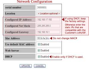
Click on the CPU serial number to open the Network Configuration page for the CPU that you want to configure.

-
Enter the Network information . . .
-
Location (optional) - enter something logical that identifies the panel location.
-
CPU network settings enter values that are appropriate for the Customer’s network.
-
if using a Static IP (recommended): Enter the IP Address, Subnet Mask, and Gateway
-
if using DHCP: skip the IP network address fields.
(In TeraTerm, you can skip fields without making changes by pressing the enter key.)
-
-
MAC Address: do not change the mac address
-
“check” Use Default MAC Address
-
“check” Enable Web Server
-
“check” Use DHCP ** only check this if you are using DHCP **
-
-
Click the UPDATE button to save the network settings in the CPU Board.
-
Click the All Panels Summary hyperlink to return to the All Panels Summary page.
-
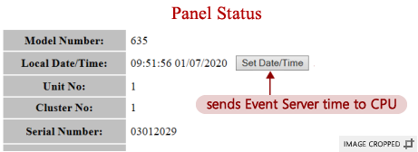
To open the Panel Status page, click the active IP Address that is beside the CPU Serial Number.

-
On the Panel Status page, click the Set Date/Time button (to sync CPU date/time).
-
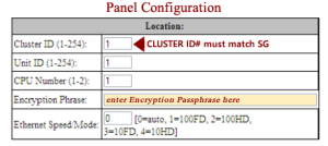
Click the Panel Configuration hyperlink ( scroll down to see the link ) ...
-
Enter the Cluster ID - must match “ID#” from System Galaxy Loop/Cluster Programming screen.
-
Enter the Unit ID (must be unique within Cluster; 0 is not valid).
-
Enter the Loop Group ID “0” (do not change if shown; should be zero)
-
Enter the CPU number “1”
-
Enter the Encryption Passphrase (enter phrase from Onboarding Document)
-
Enter Ethernet Speed “0” (automatic is recommended)
-
-
Program Panel Options as follows ...
-
“check” Enable encryption all traffic
-
“check” Enable web server
-
“check” Obtain IP Dynamically (check this only if using DHCP)
-
“uncheck” Extended Card Format

-
-
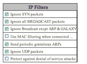
Program the panel IP Filters as follows ...
-
“check” Ignore SYN packets
-
“check” Ignore all BROADCAST packets
-
“check” Ignore BROADCAST except ARP & GALAXY
-
“uncheck” Use MAC filtering when connected to event server
-
“check” Send periodic gratuitous ARPs
-
“check” Ignore UDP packets
-
“uncheck” Protect against denial of service attacks
-
-
Program Event Server as follows ...
-
“check” Server 1 to use/connect to this Event Server IP Address
-
enter the Local TCP Port# ‘3001’ into the 635-Port field
-
enter the Remote TCP Port into the Server Port field (from Onboarding Document)
-
enter the IP Address (from Onboarding Document)
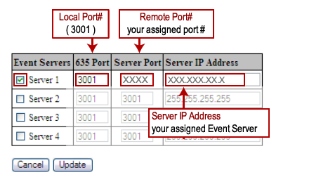
OPTIONALLY, you can set the Local TCP Port number to a unique value on each controller within the same cluster.
-
-
“uncheck” the options to use Server 2, Server 3, Server 4, unless you are adding a redundant server.
Redundant Server information will be in the Onboarding Document. -
Click UPDATE button to save these changes to the CPU.
Installing Daughter Boards
This section covers installing daughter boards into the controller panel.
IMPORTANT REQUIREMENTS:
-
Board IDs must be valid and unique on the data-bus (1-16 is valid; no duplicates allowed).
-
635-Series Boards: You must set the Board ID BEFORE you install the board using the on-board dipswitch.
-
600-series Boards: You will set the Board ID AFTER installing (using the config tool or web-page).
-
See the 635 Hardware Install Guide (Chapter 2 Step 4.2.3) in for details on setting 635-DRM dipswitch.
-
Set the Board ID for your 635-series Board using the on-board binary DIP Switch .
BEST PRACTICE: Number the first board to ID# 1. Then increment each board ID from there to be a unique ID # 2, 3, 4, etc. -
Install the Daughter Board into the next available board slot after the CPU.
-
Loosen stand-offs in the board slot.
-
Install the board by placing the mounting bracket under the standoffs and flush to the back wall of the cabinet. The surface components on the circuit board should be facing toward the battery. The power connector should be on the same side as the wiring harness.
-
Tighten the standoffs on top of the mounting bracket to secure the board inside the panel.
-
Connect the Data Ribbon Cable from the CPU to the daughter board’s data port. (Chapter 2 Step 4.2 of Hardware Guide )
-
-
Attach power wires (harness) to the orange connector and plug the connector into the Daughter Board – observing polarity! (Chapter 2 Step 3 of Hardware Guide )
-
Warm Reset the board by pressing the Reset switch (SW1).
-
Repeat these steps for each board.
Configuring Boards and Verifying Board Flash
This section describes how to configure Daughter Boards using the 635 Web Configuration Tool. However you can use the direct connect method with a serial terminal emulator is necessary.
NOTICE: It takes up to 60 seconds for board to appear on Data Bus after ribbon cable is attached. The daughter board must have power applied and a unique, valid board ID.
-
Open the Panel Status page in your browser by entering the CPU’s IP Address that you configured in the previous steps.
-
For 635-model Board(s): you should see your 635-series board(s) in the Boards Table. The 635-series Boards should display the Board ID of the on-board binary dipswitch. You should have pre-configured a valid ID before installing the board into the controller panel.
-
For 600-model Board(s): you should see your 600-series board(s) in the Boards Table. 600-series Boards will display their factory default Board ID.
You must now configure a valid ID using the following steps ... -
Click on the Board Serial number link to open the Board Configuration page.
-
Enter a Board ID that is valid and unique (unused) on the data bus (1-16 valid, no duplicates allowed).
-
Click the UPDATE button to save the Board ID.
-
Return to the Panel Status page.
-
In the Panel Status page, compare the flash version of each daughter board with the CPU flash version.
-
All Daughter Board flash must match the CPU Board flash.
-
Click the [Clear Auto-Update Timers] button to update flash on all daughter boards.
-
The board Status should return to “Normal” after flashing is completed.
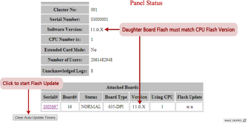
NOTE: The screen shot above is only an example. Therefore, keep in mind that certain values, like Flash Version, Event Server IP Address, and Server Port# should always match whatever your On-boarding Document says. In this screen you will sync daughter boards with the CPU version. If the CPU version needs updating, that is done in SG software (a future step).
-
-
Next, verify that the CPU Status is “Connected” to the first Event Server (No. 0 in the Event Server Table).
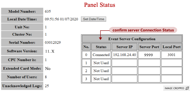 Troubleshooting Tip: if the CPU is not connected to the event server, go back to the previous instructions and verify that you have the correct IP Address and the Remote TCP Port for the Event Server. Also verify that you have the correct Passphrase configured. Make sure the CPU Board IP Network settings have the correct IP Address, Subnet, Gateway.
 -
At this point you can connect the field wiring to the daughter boards as appropriate (e.g., for readers, doors, locks, surge suppression diodes, inputs, outputs, etc.).
See Reader Wiring Guide for details concerning the type of reader you are installing. -
Jumper-out unused contacts, as follows ...
-
DRM board: If Door Contacts are not installed, you must jumper-out CNT to GND.
-
CPU board: If Low Battery wiring is not installed, you must jumper-out Low Batt to GND.
-
CPU board: If AC Fail wiring is not installed, you must jumper-out the AC Fail to GND.
-
-
Now you are ready go to the System Galaxy software and Import your Controller from the Loop Diagnostics screen.
-
All daughter boards must be powered on and connected to the CPU I2C-Data (ribbon cable).
-
Boards and field hardware are configured in their Properties screens - such as Reader, Input, and Output ...
-
NEXT TOPICS